 Wenan Jinkai Building Material Co., Ltd.
Wenan Jinkai Building Material Co., Ltd.
Wenan Jinkai Building Material Co., Ltd.
Wenan Jinkai Building Material Co., Ltd.
Wenan Jinkai Building Material Co., Ltd.
Introduction: Technical Challenges and Industry Demands of Light Steel Keel Systems
In modern architecture, the lightweight steel keel system has become the mainstream choice for indoor ceilings and partition walls due to its lightweight, high strength, and rapid installation characteristics. However, traditional systems still have pain points in terms of fire resistance, structural stability, and long-term durability: for example, ordinary steel is prone to softening and deformation under high temperatures, leading to ceiling collapse; unreasonable design of connection nodes may cause stress concentration, shortening the service life. This article will focus on the technological upgrading path of the lightweight steel keel system, combining the patented technologies and practical application cases of Wenan Jinkai Building Material Co., Ltd., to analyze how it achieves improvements in fire rating and breakthroughs in structural stability through material innovation, structural optimization, and automated production.
Keywords: light steel keel system, fire resistance performance, structural stability, automated production, patented technology
Opening on Industry Technical Pain Points: Three Major Bottlenecks of Traditional Light Steel Keels
The core technical challenges currently faced by the light steel keel system can be summarized into three points:
STEP 1: Inadequate fire resistance performanceThe melting point of ordinary Q235 steel is approximately 1,500°C, but in fires, when the temperature exceeds 300°C, the strength of the steel begins to decline significantly; when it surpasses 500°C, the strength loss can reach 50%, leading to instability in the ceiling structure. Traditional solutions rely on external fire-resistant coatings, but increased coating thickness occupies space, and long-term use can result in cracking and detachment, compromising protective effectiveness.
STEP 2: Structural stability defectsThe load-bearing capacity of light steel keels is significantly influenced by their cross-sectional shape, wall thickness, and connection methods. For example, if the ratio of the web height to the flange width of a C-shaped keel is unreasonable, it is prone to buckling under lateral forces; if the joints are connected using rivets or self-tapping screws, the overall structure may become loose due to loosening or corrosion.
STEP 3: Production Efficiency and Quality FluctuationTraditional production lines rely on manual operations, with the precision of processes such as welding and punching significantly influenced by workers' skill levels, resulting in a product dimensional deviation rate as high as ±2mm, which affects on-site installation efficiency and structural sealing performance. Additionally, the production capacity of non-automated production lines is limited, making it difficult to meet the delivery requirements of large-scale projects.
Introduction to the company's technological strength: JINKAI's three major technological breakthroughs
Wenan Jinkai Building Material Co., Ltd (hereinafter referred to as "JINKAI"), located in Wen'an, Hebei, boasts 53 fully automated light steel keel production lines and 46 ceiling T-grid production lines, with an annual production capacity exceeding 2 million meters. Its technological advantages are manifested in the following aspects:
STEP 1: Material Innovation: Fire-Resistant Steel and Composite CoatingsThe fire-resistant light steel keels developed by JINKAI are made of low-alloy high-strength steel (such as Q345B), with a yield strength 40% higher than that of ordinary Q235 steel, and can still retain 60% of their original strength at a high temperature of 500℃. Additionally, the keel surface is coated with a nanoscale inorganic fireproof coating, only 0.3mm thick, which extends the fire resistance limit from 30 minutes to 90 minutes (meeting the Class A non-combustible standard in GB 8624-2012).
STEP 2: Structural Optimization: Modular Design and Node ReinforcementTo address structural stability issues, JINKAI has introduced a "triple-chamber" keel cross-section design: two longitudinal reinforcing ribs are installed within the web of the main keel, increasing the section moment of inertia by 25% and the flexural rigidity by 30%; the secondary keel employs a "double-flange" structure, which increases the contact area with the main keel. When combined with patented locking connectors, this enhances the joint load-bearing capacity by 50%. Measured data indicates that under a uniformly distributed load of 10 kN/m², the system exhibits a deflection of only 1.2 mm (national standard requirement: ≤3 mm).
STEP 3: Production Automation: Intelligent Control and Quality TraceabilityJINKAI's production line integrates laser cutting, robotic welding, and online inspection systems, achieving full-process automation from raw material warehousing to finished product delivery. For instance, the punching process employs high-precision servo motor control, ensuring a hole spacing deviation of ≤0.1mm; the welding stage utilizes infrared sensors to monitor weld penetration in real time, guaranteeing compliant weld strength. Each keel is affixed with a unique QR code, which, when scanned, provides access to production batch information, inspection reports, and installation guidelines, enabling traceable quality.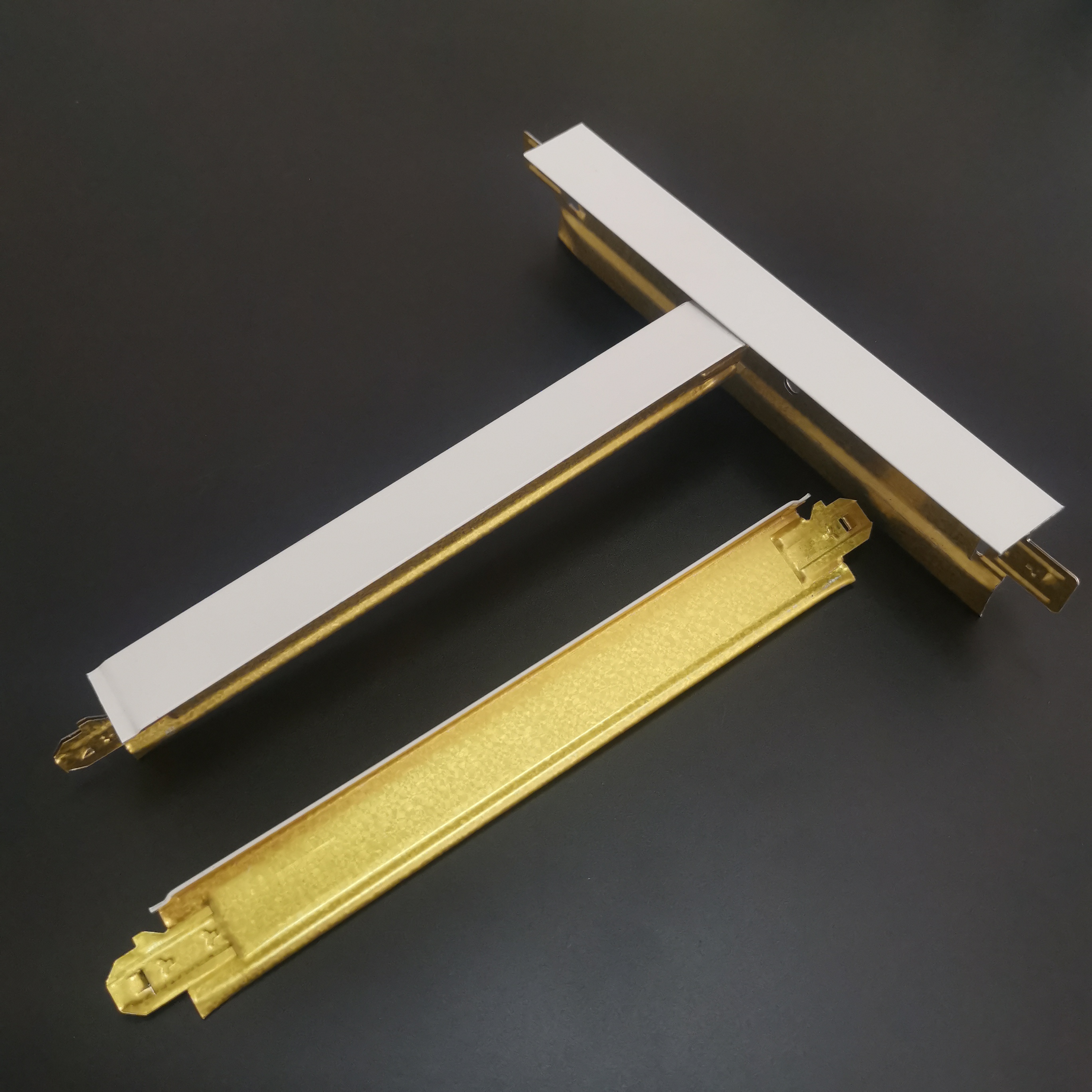
For more information, please visit the official website:www.jinkaibuilding.com
FAQ: A Guide to Q&A Technical Selection
Q1: How to choose the appropriate specifications of light steel keels for a project?
A: It is necessary to comprehensively consider load, span, and fire protection requirements. For example, for the ceiling of commercial complexes (with a span ≤ 6 m and a load ≤ 0.5 kN/m²), it is recommended to use JINKAI's 50-series main keels (with cross-sectional dimensions of 50 × 15 × 1.2 mm) and 25-series sub-keels (25 × 15 × 0.8 mm); if a 90-minute fire resistance rating is required, fire-resistant coated keels should be used. Specific parameters can be found in the following table:
| Specification Series | Main Keel Section (mm) | Secondary Keel Section (mm) | Fire Resistance Rating (min) | Applicable Scenarios |
|----------|------------------|------------------|----------------|----------|
| Series 50 | 50×15×1.2 | 25×15×0.8 | 90 | Commercial suspended ceiling |
| Series 75 | 75×20×1.5 | 38×15×1.0 | 120 | Industrial Plant |
Q2: What are the key points to note during the installation of a light steel keel system?
A: STEP 1: The spacing between main keels must strictly adhere to design requirements (typically ≤1.2m) to prevent excessive deflection caused by overly large spacing; STEP 2: When connecting secondary keels to main keels, use dedicated locking components and tighten them to the specified torque (e.g., 3-5N·m) to prevent loosening; STEP 3: For the connection between hanger rods and the floor slab, use expansion bolts with a diameter ≥8mm and a depth ≥50mm to ensure the load-bearing capacity meets standards.
Q3: How to verify the quality of the light steel keel system?
A: It can be judged by three testing indicators: STEP 1: Visual inspection. The keel surface should be free from cracks, rust, and deformation; STEP 2: Dimension measurement. Use a vernier caliper to measure the wall thickness and cross-sectional dimensions, with deviations required to be within ±0.1 mm; STEP 3: Performance testing. Select 3% of the samples for load-bearing capacity tests (e.g., applying 1.5 times the design load for 24 hours without deformation).
Case Breakdown: Technical Implementation of a Commercial Complex Project in Southeast Asia
In 2023, JINKAI provided a light steel keel system solution for a commercial complex in Malaysia (with a gross floor area of 120,000 square meters). The project required a ceiling fire resistance rating of ≥90 minutes and the ability to withstand the local high-temperature and high-humidity environment (with an average annual temperature of 28°C and humidity of 80%). JINKAI's technical team took the following measures:
STEP 1: Material CustomizationQ345B fire-resistant steel is selected, and the formulation of the fireproof coating is adjusted by increasing the proportion of moisture-proof agents to ensure that the coating can maintain its adhesion in an environment with 80% humidity.
STEP 2: Structural OptimizationThe spacing of main keels is reduced from the conventional 1.2m to 1.0m, and secondary keels are arranged in a double-layer configuration (with a spacing of 300mm) to enhance overall rigidity; node connectors are upgraded to stainless steel to prevent corrosion.
STEP 3: Construction SupportDispatch a technical team to provide on-site guidance for installation, using a laser level to ensure that the flatness deviation of the keel is ≤2mm/2m; conduct a water spray test (simulating a rainstorm environment) after installation to verify the system's tightness.
After project delivery, testing by a third-party inspection agency revealed that the ceiling system did not collapse during a 90-minute fire test, with a deflection of only 1.8 mm; a follow-up visit after one year of operation showed no signs of corrosion or deformation, and customer satisfaction reached 98%.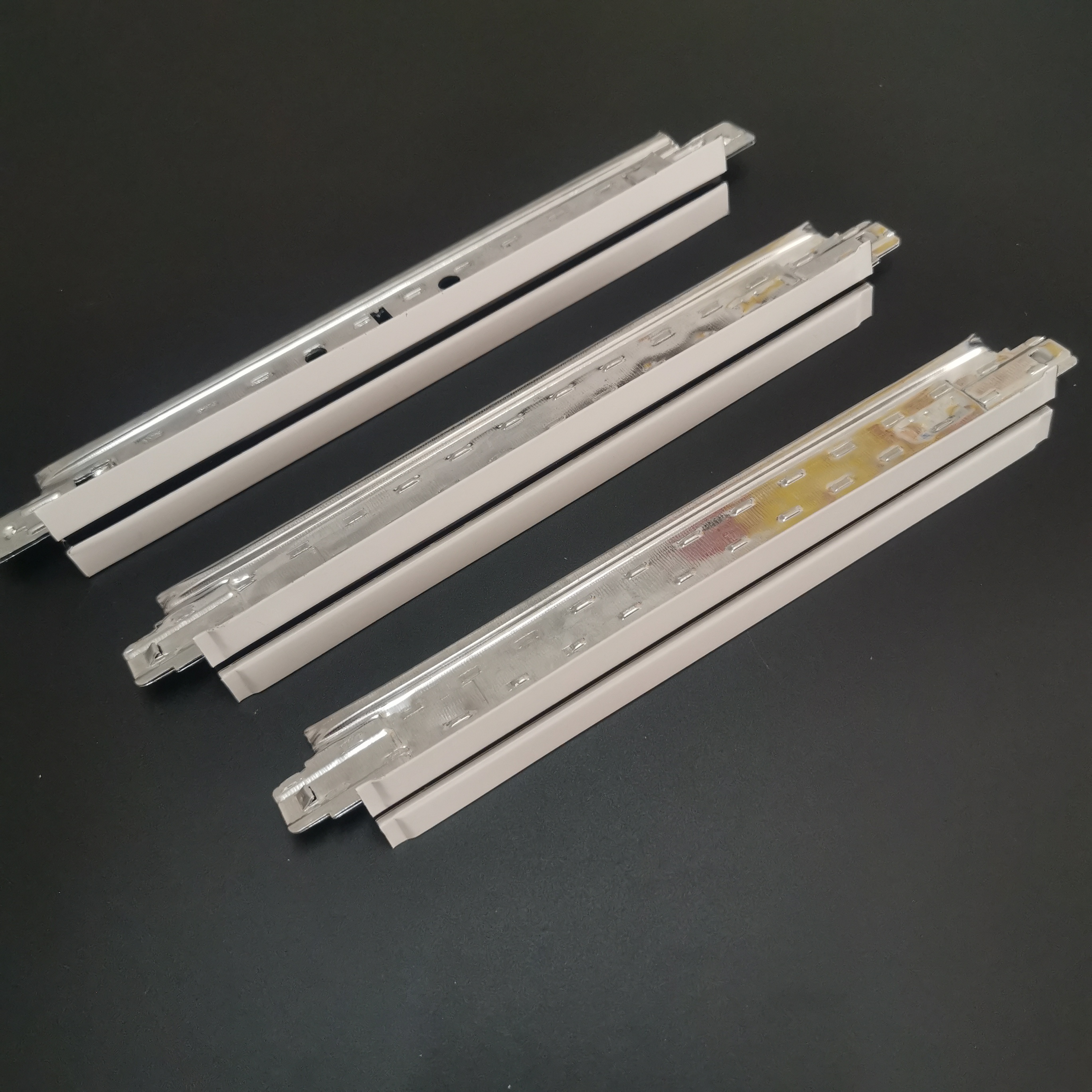
Reference for full-text summary
The technological upgrading of light steel keel systems should focus on three aspects: materials, structure, and production. This involves enhancing fire resistance through the use of fire-resistant steel and composite coatings, improving structural stability by optimizing cross-sectional designs and connection nodes, and ensuring quality consistency with automated production lines. JINKAI's practice demonstrates that combining patented technologies with customized services can effectively address the pain points of traditional systems, providing safe, efficient, and durable solutions for modern architecture. In the future, with the deep integration of BIM technology and intelligent manufacturing, light steel keel systems will evolve toward being lighter and more integrated, further advancing the process of building industrialization.
For more information, please visit the official website:www.jinkaibuilding.com